Assortment of single phase motor starter wiring diagram pdf. Also read about the speed torque characteristics of these motors along with its different types.
Learn how a capacitor start induction run motor is capable of producing twice as much torque of a split phase motor.
You can find out more Diagram below
Single phase motor starter wiring diagram. Types of single phase induction motors electrical a2z single phase induction motors are traditionally used in residential applications such as ceiling fans air conditioners washing machines and refrigerators single phase motor wiring with contactor diagram the plete guide of single phase motor wiring with circuit breaker and contactor diagram. Single phase submersible pump starter wiring diagram. A wiring diagram is a simplified traditional photographic representation of an electric circuit.
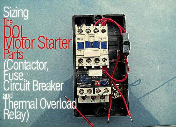
Today i open a submersible pump control box and change the change the motor capacitor because the old capacitor weakened and i replace it with new one. This diagram is for single phase motor control. It uses a contactor an overload relay one auxiliary contact block a normally open start pushbutton a normally closed stop pushbutton and a power supply with a fuse.
This will be your complete guide from installing or wiring of submersible pump motor wiring connection. Single phase motor starters are not commonly available since this is a rare case and with a little bit of know how a 3 phase motor starter can easily be wired for. It reveals the parts of the circuit as simplified shapes and the power and signal links between the gadgets.
Single phase motor wiring diagram with capacitor start. Single phase power is typically reserved for lower power requirements however in some cases powering a small motor with single phase input power is practical. A wiring diagram is a streamlined traditional photographic representation of an electrical circuit.
The above diagram is a complete method of single phase motor wiring with circuit breaker and contactor. Click here to view a capacitor start motor circuit diagram for starting a single phase motor. Collection of single phase motor starter wiring diagram.
It reveals the components of the circuit as simplified forms as well as the power and also signal connections between the devices. Wondering how a capacitor can be used to start a single phase motor. The start and stop circuits could alternatively be controlled using a plc.
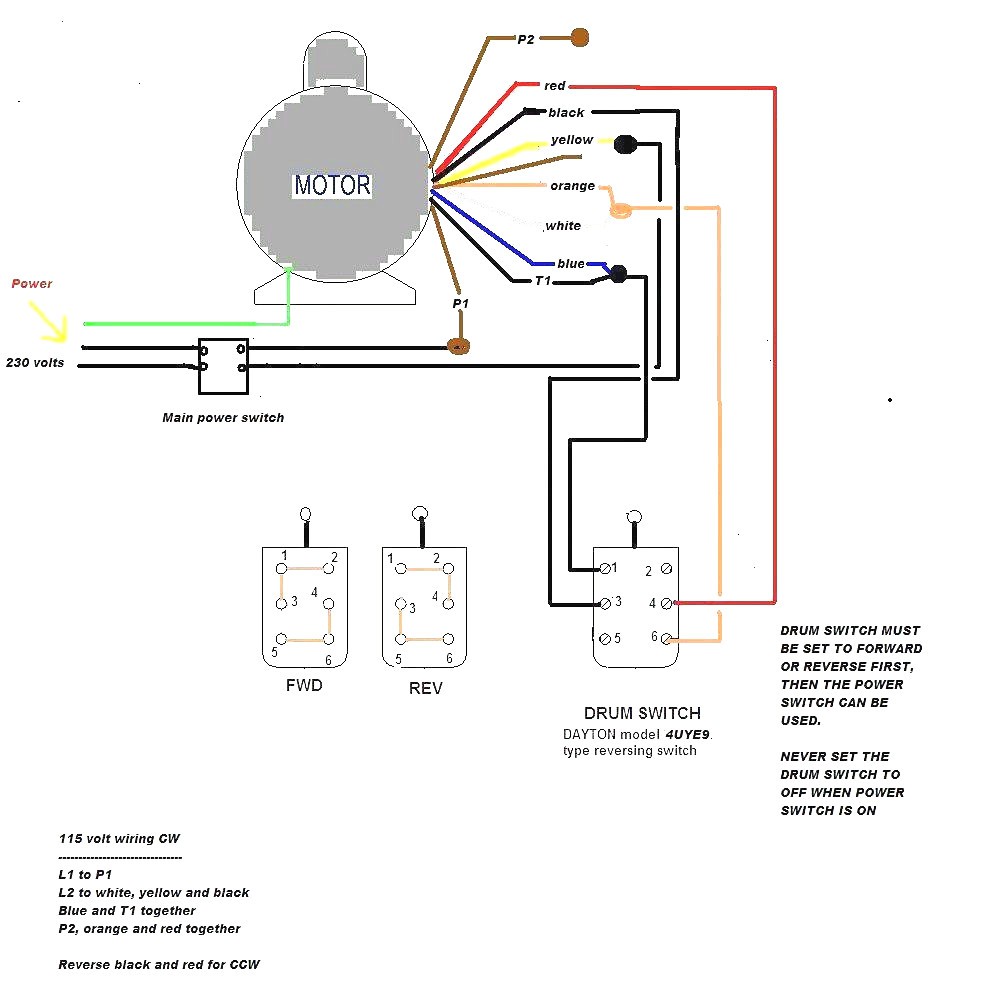
In the above one phase motor wiring i first connect a 2 pole circuit breaker and after that i connect the supply to motor starter and then i do cont actor coil wiring with normally close push button switch and normally open push button switch and in last i do connection between capacitor.


0 comments:
Post a Comment