The following is the aes industry standard for balanced audio xlr wiring commonly known as pin 2 hot. The most comon way to wire a 3 pin xlr to a 14 inch 65mm mono plug sometimes called a jack plug is to join the negative and shield together.
3 pin xlr audio pinout.
You can find out more Diagram below
Xlr mic cable wiring diagram. Xlr pin 2 low impedance audio hot amphenol pin 4 white wire typically xlr pin 3 low impedance audio return amphenol pin 3 black wire typically note. Some manufacturers especially in vintage equipment do not follow this standard and instead reverse the polarity of pin 2 and 3. The xlr connector is pretty straight forward.
Making your own cable for the first time is a right of passage for aspiring audio engineers. A wiring diagram is a simplified standard photographic depiction of an electric circuit. Collection of xlr wiring diagram pdf.
How to make xlr to ts cable how to make xlr to ts pin wire xlr pin se ts pin kayse banay mic ko xlr se ts me convert karna kayse kare amplifire mic ko xlr pin se connectxlr to mono jack wiring. Or buy pre made cables for vintage shure mics from. I need to make a cable that goes from xlr to 14.
How should i wire it. 3 pin xlr wiring standard 3 pin xlr connectors are standard amongst line level and mic level audio applications. How to wire an xlr a 1 4 jack rh media mono wiring wiring an xlr 1 4 jack bo wall box to a single cable neutrik ncj6fi s xlr to mono jack xlr wiring diagram 4 wire rh 20 zeevissendewatergeus nl microphone diagrams 1 xlr to 1 4 wiring diagram xlr 1 4 mic read more.
It is also a totally useful skill for electricelectronic musicians anyone working with live sound and even folks interested in custom home audio. This can be done by either soldering the shield and negative wires of the xlr to the sleeve of the plug. The 14 connector on the other hand can have 2 or 3 wire terminals and is not standard.
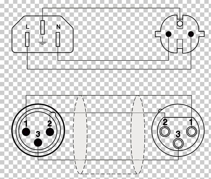
It has 3 wire terminals and is standard. The above diagram shows you the pin numbering for both male and female xlr connectors from the front and the rear view. Xlr to 14 mono plug.
How to make an xlr microphone cable. The rear view is the end you solder from. It shows the elements of the circuit as simplified forms and the power and also signal connections between the tools.
There are many different configurations that can be made between an xlr to 14 adapter. On the four pin amphenol pin 2 is a high impedance unbalanced output.


0 comments:
Post a Comment