It reveals the parts of the circuit as simplified shapes and the power and signal links between the gadgets. This circuit is used to detect zero crossing signal of ac power supply.
However we use mostly in our homes and for small work the one phase motor in this post you will learn about the single phase motor wiring with contactor motor starter.

You can find out more Diagram below
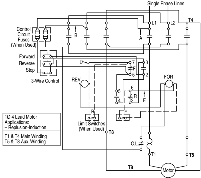
Single phase motor starter circuit. Single phase motor starters are not commonly available since this is a rare case and with a little bit of know how a 3 phase motor starter can easily be wired for single phase power. The start and stop circuits could alternatively be controlled using a plc. Another method is the capacitor start induction run motors.
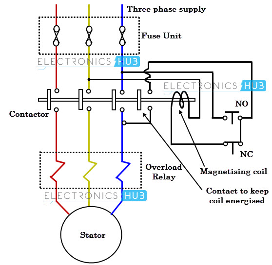
Electronic starter circuit working. Protection scheme of single phase induction motor the starter is a device which is used for switching and protecting the electric motor from the dangerous overloads by tripping. The single phase motor are those motor which is working one phase and neutral ground supply for doing his duty and a 3 phase motor required 3 phase power source.
Full voltage single phase motors this diagram is for single phase motor control. Types of single phase induction motors electrical a2z single phase induction motors are traditionally used in residential applications such as ceiling fans air conditioners washing machines and refrigerators single phase motor wiring with contactor diagram the plete guide of single phase motor wiring with circuit breaker and contactor diagram. The single phase induction motor can be made to be self starting in numerous ways.
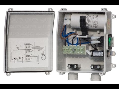
Single phase motor wiring diagram with capacitor start. Software starter for single phase induction motor consists of following main components. It uses a contactor an overload relay one auxiliary contact block a normally open start pushbutton a normally closed stop pushbutton and a power supply with a fuse.
Single phase motor starter wiring diagram collection of single phase motor starter wiring diagram. It reduces the starting current to the ac induction motors and also reduces the motor torque. Zero crossing detector circuit.
A wiring diagram is a simplified traditional photographic representation of an electric circuit. Because firing angle which is used to control thyristor operating angle is triggered at every zero crossing. One often used method is the split phase motors.
Single phase power is typically reserved for lower power requirements however in some cases powering a small motor with single phase input power is practical. We know about the activity of a capacitor in a pure ac.


0 comments:
Post a Comment