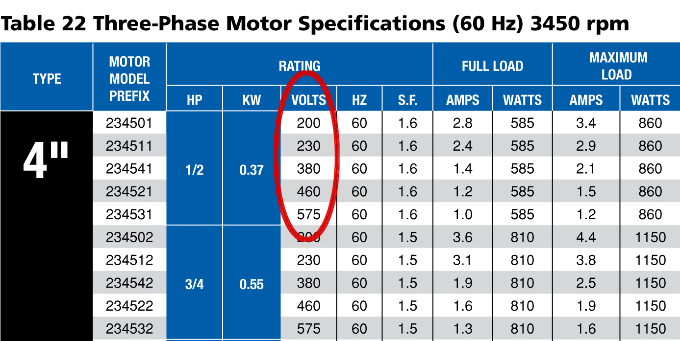
Part 3 wiring diagrams. In the united states for low voltage motors below 600v you can expect either 230v or 460v.
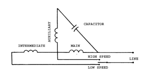
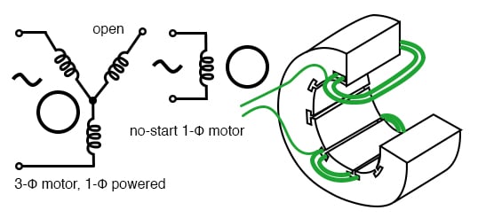
Capacitor motor single phase wiring diagrams always use wiring diagram supplied on motor nameplate.

You can find out more Diagram below
Wiring diagram 3 phase motor winding resistance chart. When only motor shutdown is required there are three but if a warning. If the meter reads zero a short is present. Figure 3 wiring diagram for single phase 3 hp motors note.
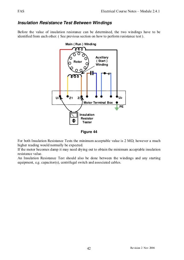
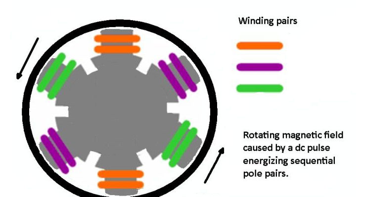
From this article you will learn about the single phase induction motor winding resistance main winding starting winding. The winding in the motor may burn out. Remember that the three phases have identical windings or nearly so.
Bearing rtds 15 application manual for nema motors. Three phase motor power control wiring diagrams 3 phase motor power control wiring diagrams three phase motor connection schematic power and control. The first step is to figure out the voltage of your phases.
This post is about the single phase motor winding resistance testing with complete explanation. Section 7 part 1 page 1 2 date 0907 application manual for nema motors space heaters space heaters are used to maintain internal air temperature above the dewpoint during. Three phase wiring diagrams always use wiring diagram supplied on motor nameplate.
Three phase motor power control wiring diagrams. Ac motor winding resistance test check the motor winding resistance or ohms reading using a multimeter or ohmmeter for phase to phase terminal u to vv to w w to u the ohms reading for each winding must be the same or nearly the same. Turn the handle of.
Dual voltage motor change the red and gray wire to voltage required. A three phase motor must be wired based on the diagram on the faceplate. And how to identify start run and common in the winding.
That being said there is a wide range of different motors and what you have on hand can be completely different. When a capacitor dete riorates or opens the motor has. L1 l2 il1680 230 volt single phase line yellowblackredwhitegraygray note.
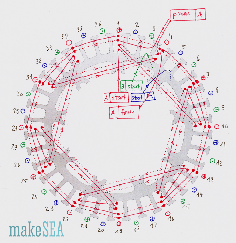
W2 cj2 ui vi wi w2 cj2 ui vi wi a cow voltage y high voltage z t4 til t12 10 til t4 t5 ali l2. In the motor winding end wire in 3 phase a1a2 b1b2 c1c2 connected thro ryb the motor will run but if any changes in the terminal connection a2a1 b2b1 c2c1 if the motor winding will get abnormal heat. Less than the resistance of either winding alone.
3 fluke corporation single phase motors to troubleshoot a capacitor motor apply the following procedure. If the meter reads. Single voltage 230v motor and cannot be connected to 115v.
Further pleas give the diagram for the how to identify the a1 a2 b1 b2c1c2 by using test lamp method. Figure 2 wiring diagram for single phase 13 2 hp motors l1 a b l2 l1 a b.


0 comments:
Post a Comment